
- Posts: 183
A Sopwith Bevel-box Puzzle
- Paul
- Topic Author
- Offline
Less
More
1 year 9 months ago - 1 year 9 months ago #1762
by Paul
A Sopwith Bevel-box Puzzle was created by Paul
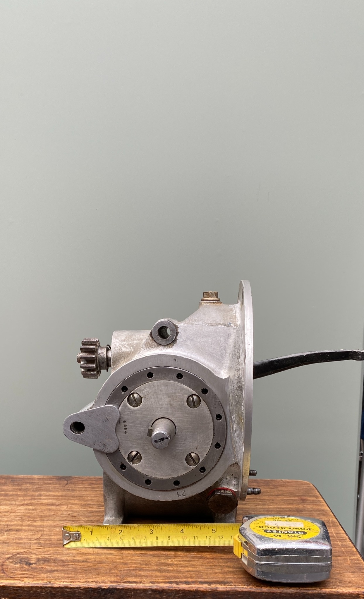
According to the Spare Parts List, the "Countershaft Housing" (G203) screws directly into the main Housing (G201), as per illustration, even if it's upside down. Its thread is 16 TPI, and it has 12 peg-holes, equally-spaced on a pitch circle.
I've seen three* such arrgts. in real life.
However, I've now seen four** arrgts. that were different! Please examine the following illustration:-
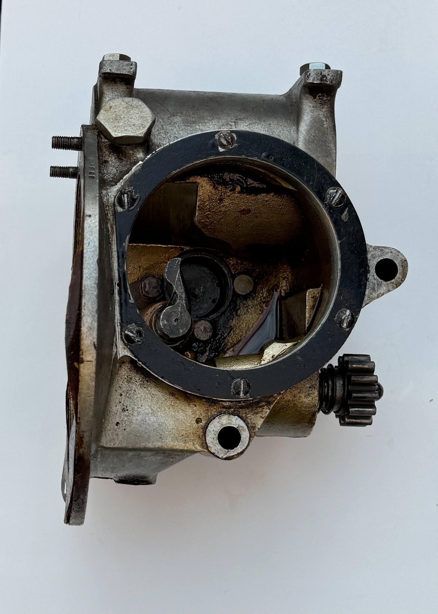
A short female-threaded flanged ring has been set into an enlarged plain hole in the main housing, and attached to it by 6 x 3/16" BSF (!) screws. The "Countershaft Housing" that screws into it is as per G203 above, with the same 16 TPI thread, but with only 10 not very equally spaced peg-holes.
Both flanged ring and Countershaft Housing carry Sopwith inspection stamps: their origin cannot be doubted. But why weren't the G203's properly finished? Clearly, the standard peg-plates ("Locking Plate for Countershaft Housing, G234") would not have fitted these G203's.
The real puzzle here is perhaps, Why were these bevel boxes modified from the standard pattern? And by whom? And where was it done?
Solutions, theories and additional information please, on a postcard or email, to the Forum, or if anonymity is desired, to pybeat@gmail.com
Less of a puzzle is the matter of the bevel-box's final drive cross-shaft ("Countershaft G218"). Its original Woodruff key, to anchor the sprocket, was so ridiculously large that it seriously weakened the outboard end of the shaft! I've come across two that were on the point of breaking, and several replacements, all home-made, with alternative keying arrgts.
* Serial nos. 1344,1592 and 2654.
** Serial nos. 2018, 2517, 2995 and 3051.
I've seen three* such arrgts. in real life.
However, I've now seen four** arrgts. that were different! Please examine the following illustration:-
A short female-threaded flanged ring has been set into an enlarged plain hole in the main housing, and attached to it by 6 x 3/16" BSF (!) screws. The "Countershaft Housing" that screws into it is as per G203 above, with the same 16 TPI thread, but with only 10 not very equally spaced peg-holes.
Both flanged ring and Countershaft Housing carry Sopwith inspection stamps: their origin cannot be doubted. But why weren't the G203's properly finished? Clearly, the standard peg-plates ("Locking Plate for Countershaft Housing, G234") would not have fitted these G203's.
The real puzzle here is perhaps, Why were these bevel boxes modified from the standard pattern? And by whom? And where was it done?
Solutions, theories and additional information please, on a postcard or email, to the Forum, or if anonymity is desired, to pybeat@gmail.com
Less of a puzzle is the matter of the bevel-box's final drive cross-shaft ("Countershaft G218"). Its original Woodruff key, to anchor the sprocket, was so ridiculously large that it seriously weakened the outboard end of the shaft! I've come across two that were on the point of breaking, and several replacements, all home-made, with alternative keying arrgts.
* Serial nos. 1344,1592 and 2654.
** Serial nos. 2018, 2517, 2995 and 3051.
Last edit: 1 year 9 months ago by Paul.
Please Log in or Create an account to join the conversation.