- Posts: 23
Oil pump and circuit
- ABC-GR-500
- Topic Author
- Offline
Less
More
2 years 1 month ago - 2 years 1 month ago #1677
by ABC-GR-500
Oil pump and circuit was created by ABC-GR-500
Hello,
I am restoring an ABC 500cc that I bought dismantled.
I don't know how the oil circuit was connected.
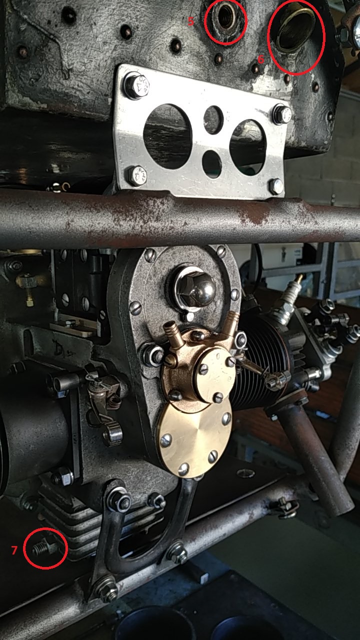
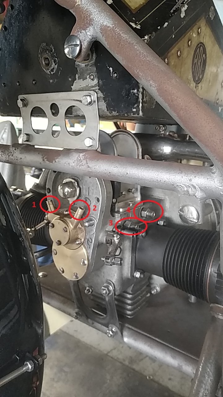
Could any of you point me to the attached photos where connect the dots identified by numbers.
Thank you so much
Bonjour,
Je restaure une ABC 500cc que j'ai acheté démontée.
Je ne sais pas comment était connecté le circuit d'huile.
L'un d'entre vous pourrait-il m'indiquer sur les photos ci-jointes ou relier les points identifiés par des numéros.
Merci beaucoup
Frédéric
Last edit: 2 years 1 month ago by ABC-GR-500.
Please Log in or Create an account to join the conversation.
- Dabney
- Offline
Less
More
- Posts: 96
2 years 1 month ago #1678
by Dabney
Replied by Dabney on topic Oil pump and circuit
The Gnome Rhone used a different oiling system to the Sopwith. I have been intrigued to understand how it works; however I do have a few pictures that may assist you.
best wishes
Ian
best wishes
Ian
Please Log in or Create an account to join the conversation.
- Dell
- Offline
Less
More
- Posts: 56
2 years 1 month ago #1679
by Dell
Replied by Dell on topic Oil pump and circuit
Hi this is from motor cycling January 18 1922,it is only a photocopy and not very clear it refers to the lamplugh oiler but may help on connections
Please Log in or Create an account to join the conversation.
- Daniel
- Offline
Less
More
- Posts: 24
2 years 1 month ago #1680
by Daniel
Replied by Daniel on topic Oil pump and circuit
Ce modèle est équipé d'une pompe simple sans limiteur de pression.
Il y a quelques fois ce limiteur sur les dernières versions car c'est une pompe volumétrique.
- Le repère N°4 est l'arrivée d'huile depuis la pompe manuelle il faut impérativement un claper sur l'arrivée de la pompe au moteur.
- Le repère N°3 correspond au reniflard il faut mettre un tube jusqu'au niveau de la tôle sous le moteur
- Le N°2 correspond au retour d'huile vers la pompe manuelle sur un diabolo qui relie la pompe au goute à goute voir photos.
- Le N°1 est l'aspiration d'huile qu'il faut relier au réservoir sous le moteur .
Il y a quelques fois ce limiteur sur les dernières versions car c'est une pompe volumétrique.
Please Log in or Create an account to join the conversation.
- ABC-GR-500
- Topic Author
- Offline
Less
More
- Posts: 23
1 year 11 months ago - 1 year 11 months ago #1701
by ABC-GR-500
Replied by ABC-GR-500 on topic Oil pump and circuit
Merci beaucoup pour toutes ces informations qui répondent à nombre de mes questions.
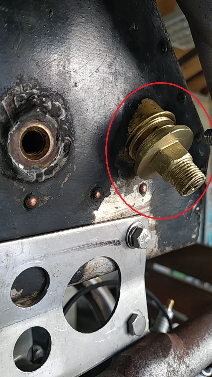
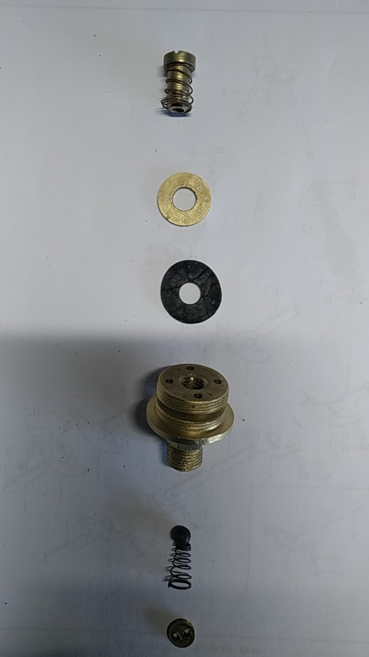
Un mécanisme devant servie à la lubrification du moteur reste néanmoins encore pour moi mystérieux. Il s'agit du mécanisme présenté sur les photos monté sur le réservoir et des-assemblé sur la seconde photo.
A quoi sert il?
Comment fonctionne t il?
Ou se connecte sa sortie?
Thank you very much for all this information which answers many of my questions.
However, a mechanism used to lubricate the engine still remains a mystery to me. This is the mechanism shown in the photos mounted on the tank and disassembled in the second photo.
What is it used for?
How does it work?
Where does its output connect?
Last edit: 1 year 11 months ago by ABC-GR-500.
Please Log in or Create an account to join the conversation.
- Dabney
- Offline
Less
More
- Posts: 96
1 year 11 months ago #1702
by Dabney
Replied by Dabney on topic Oil pump and circuit
Looking at the picture gallery on Gnome Rhone machines on this website they do seem to have a brass device on the front size of the tank; however I can see no piping connections to it. Also from what I can recall from seeing them at Montlhery and these pictures (using the numbering on your photos) 7 (sump) connects to 1(pump) (maybe acting as a scavenge to stop the sump from over filling). 2 (pump) connections into the feed side of semi automatic oil pump on the tank (maybe recirculating any excess oil from the sump), which with the main oil tank feeds the drip oil supply to the engine at 4. 3 is a crank case compression breather. 3 and 4 serve the same function on the Sopwith ABC. The Sopwith does not have the small finned sum as on the Gnone Rhone; however it does have a hole low down the side of the crank case with a one way valve that serves the same function of stopping the crankcase from over filling with oil. Hope this helps and doesn't add further confusion. best wishes Ian
Please Log in or Create an account to join the conversation.


