
Being a round-up of technical hints and observations from Paul Button's pen, that have appeared in print since 2012. .
Head Gaskets for Sopwith Machines, and specifically, How To Live Without Them!
The Inglis Parts List includes such gaskets, but I have never seen such an item, and wonder what it would look like. Skeletal, to say the least, or is it simply a slim metal ring?
Anyway, with six equi-spaced bolts on a pitch circle to hold each cylinder head to its cylinder barrel, I find any sort of gasket superfluous. Each head can easily be lapped onto its mating cylinder-top joint-face with the use of a little valve-grinding paste, to provide a true, even matt-grey surface. Thereafter, incremental and sequential tightening of the six ¼” BSF bolts to a torque of 10 N.m. (in old money that’s 90 lb.in., or 7.5 lb.ft., depending on your tackle) will give a gas-tight union. The increase in Compression Ratio won’t register on the Richter Scale, and the Decrease in Inlet and Exhaust Port Centres shouldn’t upset fitment of the manifolds, either.
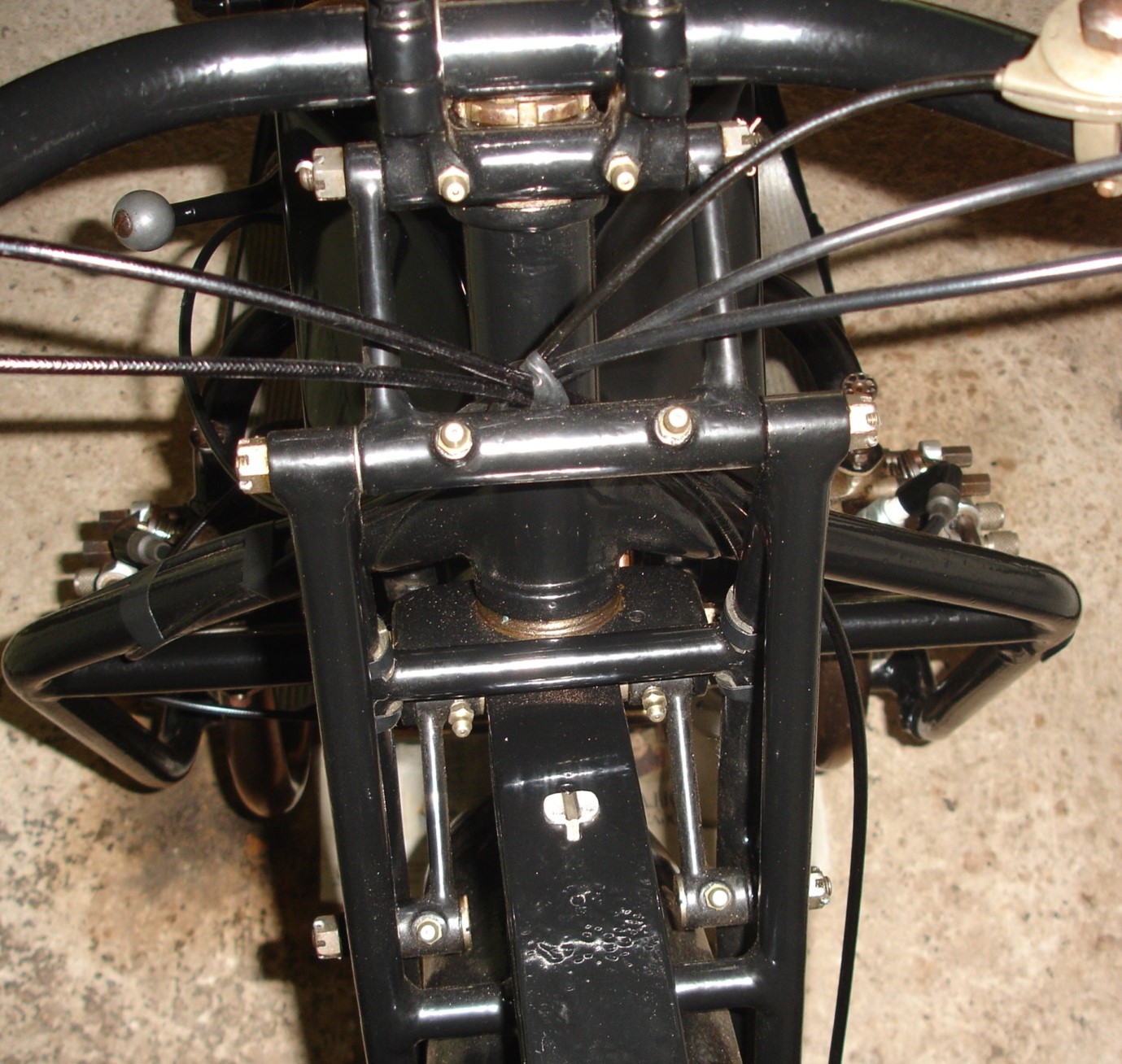
Sopwith Front Fork Spindles/Bushes.
As outlined in the VMCC Journal for February 2013, the set-up here is unusual in that the bushes move with the spindles, and it is the outsides of the bushes that form the bearing surfaces. The spindles are in fact tie-bars: they clamp-up the pairs of bushes and their central spacer tubes between the fork blades or swinglink ends to form rigid structures, with just enough shim-washers to prevent the swinglink cross-tubes etc. being clamped too. (The ‘interrupted’ spindles act as cantilevers rather than as beams, but the clamping principal is the same).
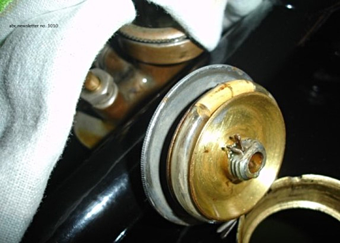
My forks felt well-worn! Quite sloppy! Mainly, I think, from indifferent maintenance, but also from indifferent lubrication! Bicycle-style oil-cups were fitted adjacent to the bearings, not grease nipples. All the bushes were oval on the outside, which matched the insides of the holes they came out of! However, it looked worse than it was: the holes all came up clean after reamering them through at dia. 17/32”. (They started life at dia ½”, so 90 years of toil had in fact been quite kind to them). New bushes were tailored up using brass: the originals were of bearing-bronze of some sort, but, because fork bearings are not in continuous rotation at elevated speeds, rather in limited oscillation at low speed, I thought it unnecessary to spoil them. Modern grease nipples were fitted, an acceptable departure from original spec., I felt. Where nipple inside-ends would have protruded through thin bearing-surrounds, the nipples were halted at less than full-engagement with araldite! See picture alongside for the final result.
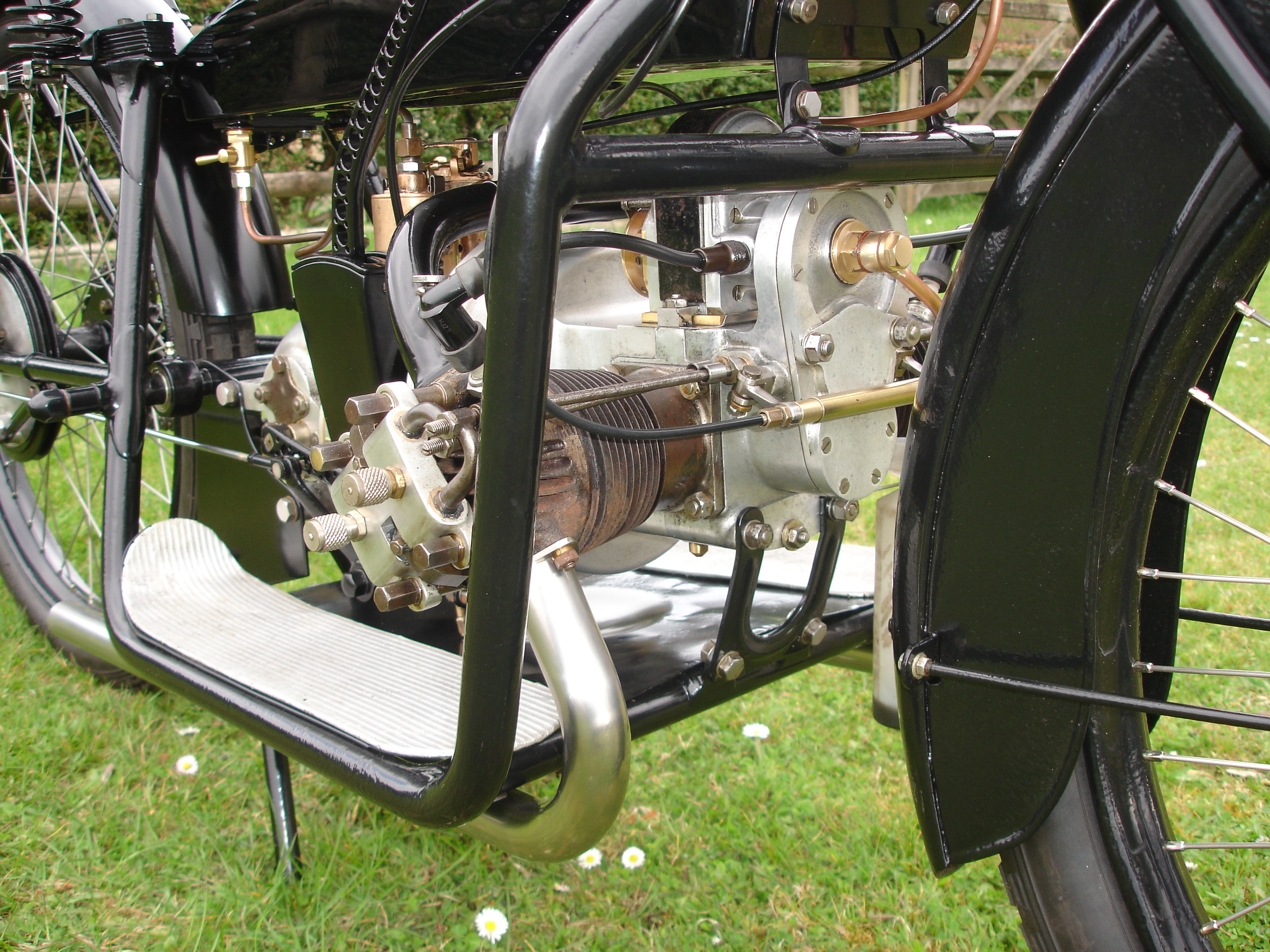
The Sopwith exhaust valve-lifter system.
This was another of those Bradshaw afterthoughts that remained unsorted: in theory it was fine, but in practice, it worked so badly that it was often discarded.
The principal problem was that the L-shaped return spring on each lifter arm wasn’t strong enough to overcome the internal friction of the Bowden cable that operated the arms. Typically, the arms couldn’t retract enough, and would be fluttered by the tappets for as long as the engine ran. If stronger springs had been fitted, all might have been well, but there was scarcely provision for the fitment even of the thin springs that were used.
My solution has been, basically, to fit a single helical compression spring coaxially round the Bowden inner cable, between the cable-ends of the lifter arms. To get the right spring characteristic, the spring is only about two inches long, and to give a neat appearance, it is enclosed within a telescopic (tube-and-plunger) housing. The present O.D. of the housing is half an inch, pending procurement of slimmer components. Because of the limited movement of the handlebar lever, and hence of the cable, reduction of lost motion to a minimum is necessary for successful operation. All that this entails, in fact, is (a) placing a suitable number of ¼” plain washers round each tappet, outboard of the crankcase and inboard of the tappet-end of each arm, and (b) adjusting the length of the cable. Although an ABC engine can usually be started without the use of a valve-lifter, stopping it is much enhanced!
Transposed cylinder heads
David Hales’ Correspondence Files include quite a lot of photos of owner’s machines, in a wide range of conditions, from As Found to Fully Restored. Among them, I was bemused to identify several with transposed cylinder heads, one with transposed cylinders, and even one with two LH heads!
Examination of my own cylinders and heads revealed the following:-
(i) Because of the partial symmetry of each cylinder head, and the similarity of its ports, it is possible to switch left- and right-hand heads with each other so that the (identical) port-faces connect up perfectly with the inlet and exhaust manifolds. However, the head fins will be at 12⁰ to the vertical, and the sparking plugs will be to the rear! Also, Jarvis or Inglis rockers will be required, as they pick up on four of the head-to-cylinder bolts, but not , as such, on the heads. Additionally, the functions of inlet and exhaust ports will have been exchanged.
(ii) Because of the approx. 6⁰ offset of the pitch-circle of six holes at the top of each cylinder (in opposite directions!), the switching of cylinders left for right is not on, if proper manifold alignment is to be achieved. It follows that the pushrods would have to work at fairly wild angles, too.
Should you notice strange head-fin angles/spark-plug locations/pushrod geometry on your machine, please refer to the above…
On a more serious note, a LH cylinder could be converted to a RH component (or vice versa) by turning the cylinder through 90⁰ and drilling and tapping a fresh set of dia. ¼” BSF holes. These would fall sufficiently far from the existing holes (at intervals of 18⁰ and 42⁰) as not to affect them. (Without the 90⁰ turn, the intervals would be 12⁰ and 48⁰).
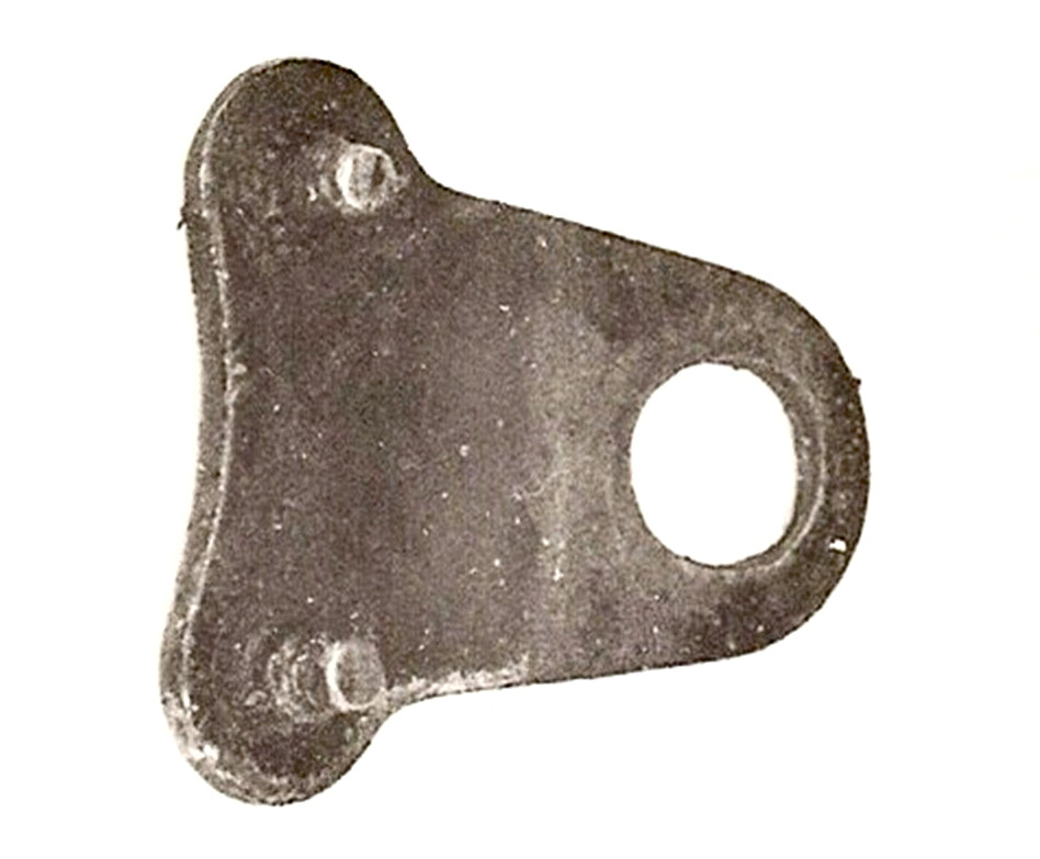
The peg-lockplate for the big adjustment ring in the bevelbox
It seems that there weren’t enough of these plates to go round, judging by some of the fearful bodges I’ve come across, as alternative attempts to lock the big ring. True to form, my own bevelbox missed such a lockplate, but didn’t need one, as the ring had been copper- and then nickel-plated on its OD, and was extremely tight. The lockplate that I free-lanced up, before I’d seen a real one, wasn’t too wide of the mark…
Both the Inglis and Jarvis Instruction books, page 17, under the heading "To Adjust the Bevel Drive", advise that "A small locking plate will be found immediately below (the Chain Guard). REMOVE THIS" (The capitals are mine). But then, no instruction is given to REFIT IT. Can this be significant?
The Correspondence Files throw up only one reference, from Albert Wallis, 6 Mar. 1980, who wrote "When I stripped the engine out of the frame, this little bit dropped on the bench, try as I may I can-not see where it goes". He added a small but unmistakeable sketch of the plate, and also The Photo (see left).
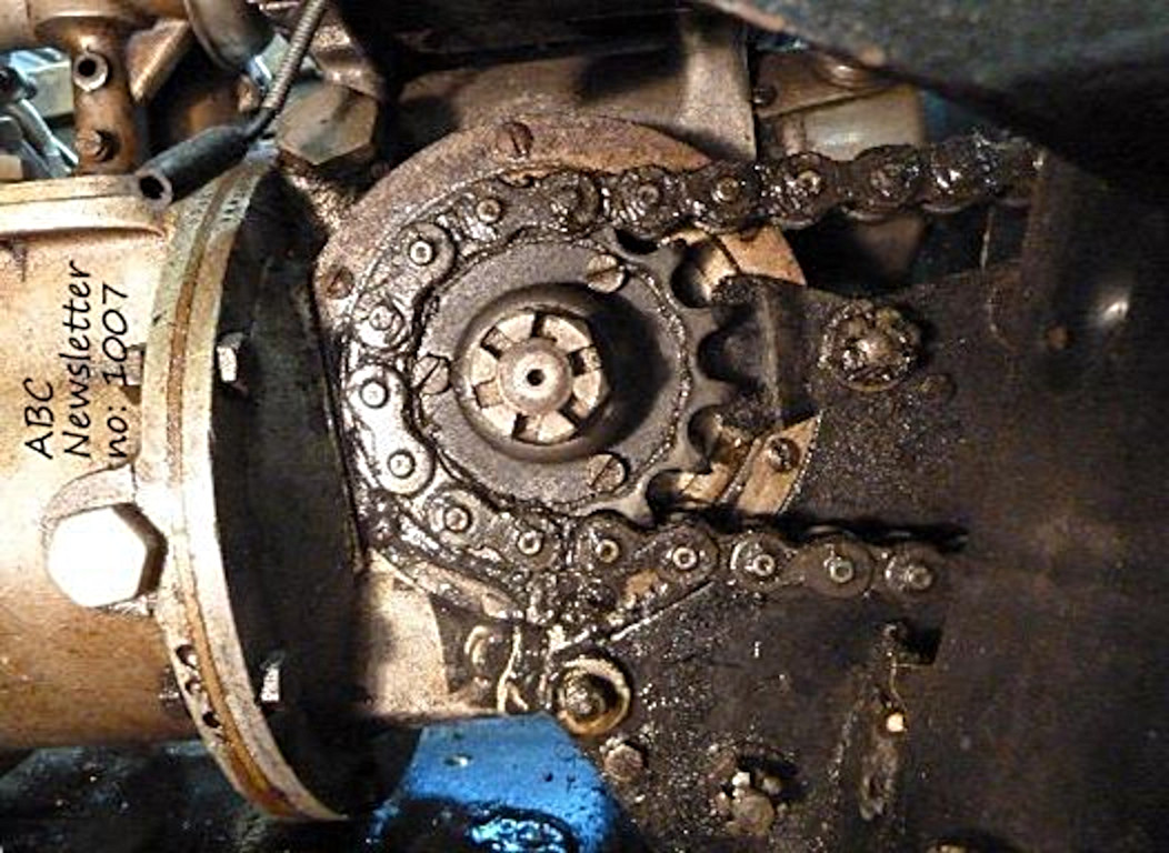
In spite of Les Taverner in his series of ABC Restoration articles of long ago making up a locking plate that he attached to a non-original bolt in the top of his bevel box, it is surely clear that a real locking plate should be anchored by one of the dia. 3/8" bevel box through-bolts. Ex-ABC Marque Specialist Alan Redman provided a picture which clearly (?) shows how the lockplate is located by the upper of the two bevel-box through-bolts.
Whilst on the subject, Gnome et Rhone adopted a different approach to this part of the machinery: instead of the output shaft bearing being carried in a large threaded ring, it was mounted in a cast plate, solidly nailed to the bevelbox by eight studs! How adjustment of the bevel gears was achieved is not immediately clear however.
Sealing Rings for petrol-tank caps
Keith can now confirm that Sealing Rings for petrol-tank caps (oval-section), made of Viton rubber, do the job satisfactorily. Well, at about £13 each (inc. P & P) they really should! My own solution to this problem (see photo alongside) costs about 10P…it consists of a few inches of dia. 6 mm. X 1 mm. polythene tubing, tailored to length, with a bit of dia. 4 mm. tubing forming a joining-link, inserted with a wipe of araldite. Petrol will very slowly harden the tubing, but at that price, who can complain?
ABC-Sopwith Screw Thread Directory
Rule No. 1: All ABC-Sopwith screw threads are to British Standard Fine (BSF) except where they aren’t.
Read on...
The original-equipment CAV type KU2 magneto favoured British Association (BA) threads. This now-archaic series featured Metric pitches, Imperial diameters, and a thread-form of 47 ½ degrees...
Of particular note is the driving-pinion’s nose bolt, originally of 0BA size (What?) However, the armature’s nose-thread can be smoothly cleaned up with an M6 tap (of identical pitch and near-identical diameter) and an M6 bolt substituted.
The timing-chest cover should be attached with 8-off 3/16” BSF fillister-headed (countersunk, raised head) screws, but this thread-size has become somewhat obsolete. In fact, more-easily obtainable 2BA screws can be fitted, without further ado (31.36 TPI v. 32 TPI, and nominally 2 thou. thinner) but shouldn’t be super-tightened. This is an officially-approved fix.
The magneto-nose access plug in this cover is to 5/8" BSP.
Ruling thread-size on the Claudel-Hobson carburettor is 5/32” BSW, including the bypass jet on the side. The intake-protector however is attached via a 1” x 16 TPI thread. Curiously, the main jet’s anchorage is M6.
The steering-head stem exhibits a 1 1/8” x 26 TPI thread.
Front and rear axle bearing-cones run on 9/16” x 26 TPI threads.
Grease-nipple holes and cable-end adjusters comply with Rule No. 1, see above.
The non-return valves and drain-plugs in the crankcase, and the fuel taps in the tank, are to 1/8” BSP. (This ”size” is misleading: in fact, the OD of these threads is close on 3/8”).
The priming cocks on the inlet manifold have 5/16" BSW threads, and their retention screws are to 4BA.
The peripheral thread of the depth-of-bevel-geartooth-engagement adjusting ring ("Housing for Countershaft G203") has a pitch of 16 TPI. [With its 12 equi-spaced peg-holes (for the "Locking Plate ..... G234") this confers an incremental axial movement of the large bevel gear of 0.00521", or 'five thou. and a bit'].
The foot-bar of the kickstarter pedal is attached to its crank-arm via a 9/16" BSF thread, but it's left-hand.
Any more?
Written by Paul Button for the Association of ABC enthusiasts.