Flat Twin Engine, 68.6 mm. x 54 mm., 398.4c.c; Four-speed Gear Box, Gate Change, and Spring Frame.
Some preliminary details regarding the A.B.C. post-war programme appeared in The Motor Cycle of November 28th, 1918, page 475. Since that date items in the 1919 programme have undergone some modification, and the engine and other parts have been considerably improved.
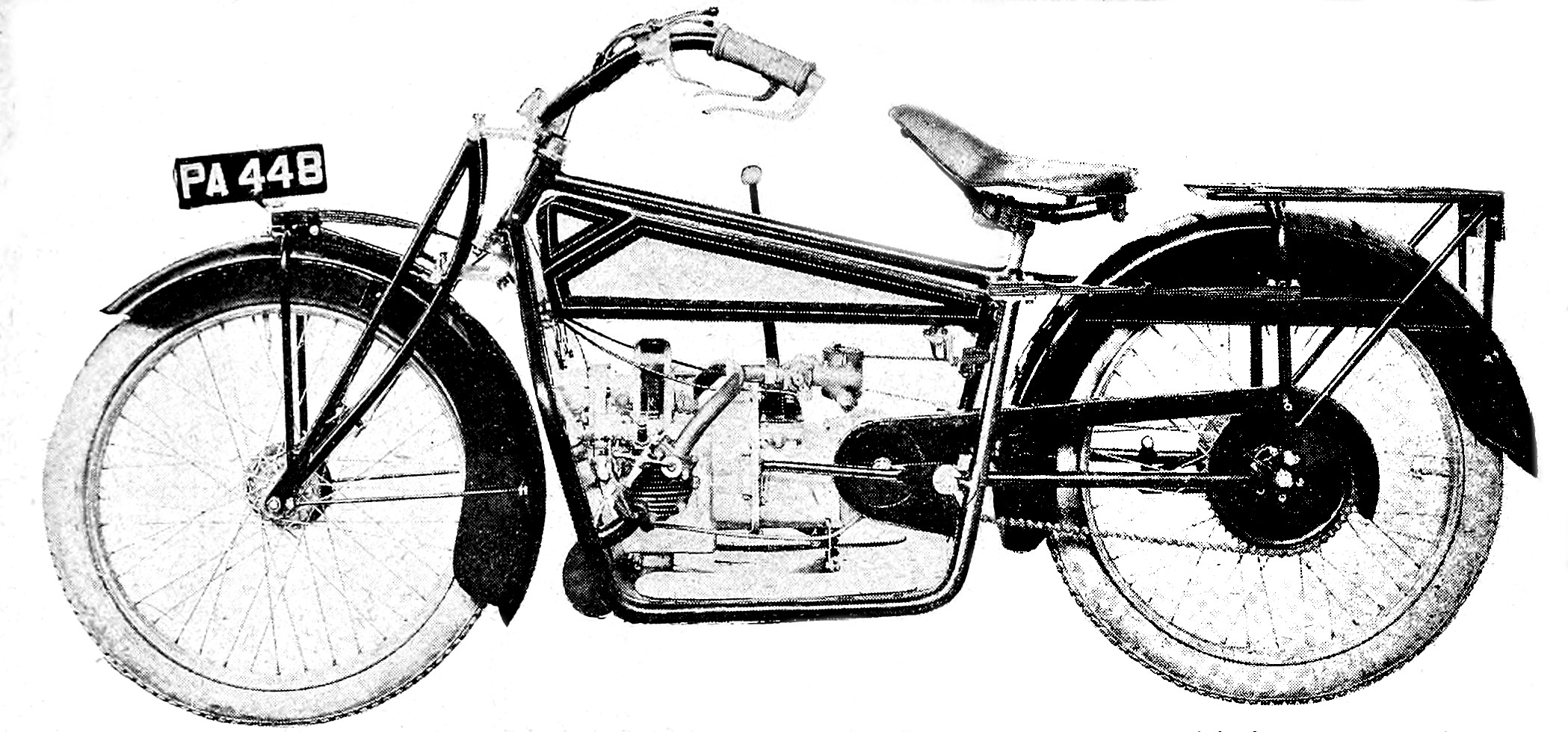
The new spring frame 3 h.p. A.B.C, the engine of which is a flat twin fitted transversely in the frame. Many of the features are revolutionary in design, yet the ensemble is decidedly attractive. - The MotorCycle, March 13th 1919.
The first impression one receives of the new A.B.C. is that it is designed as a motor bicycle. It is no slavish copy of any existing design, but a bold attempt to construct a self-propelled two-wheeler on original lines, but with no suspicion of freakishness. The designer's ingenuity has had lull play, and yet, with all its originality, there appears to be no reason why the machine should not be successful in every way.
Probably the first characteristic of the machine which strikes one is the lack of void spaces between wheels and frame and about the engine. It is a motor cycle designed around an engine gear unit rather than an over-developed bicycle fitted with an engine, and the result is most pleasing to the eye. It requires attention at one point, however, to make it conform to the ideals of a large coterie of all-weather riders. We refer to the mudguarding and the chain cover. We think the rear guard would be improved by the extension of the valance between the chain and the tyre, and that a totally enclosed chain would be better than the threequarter guard shown on the model illustrated.
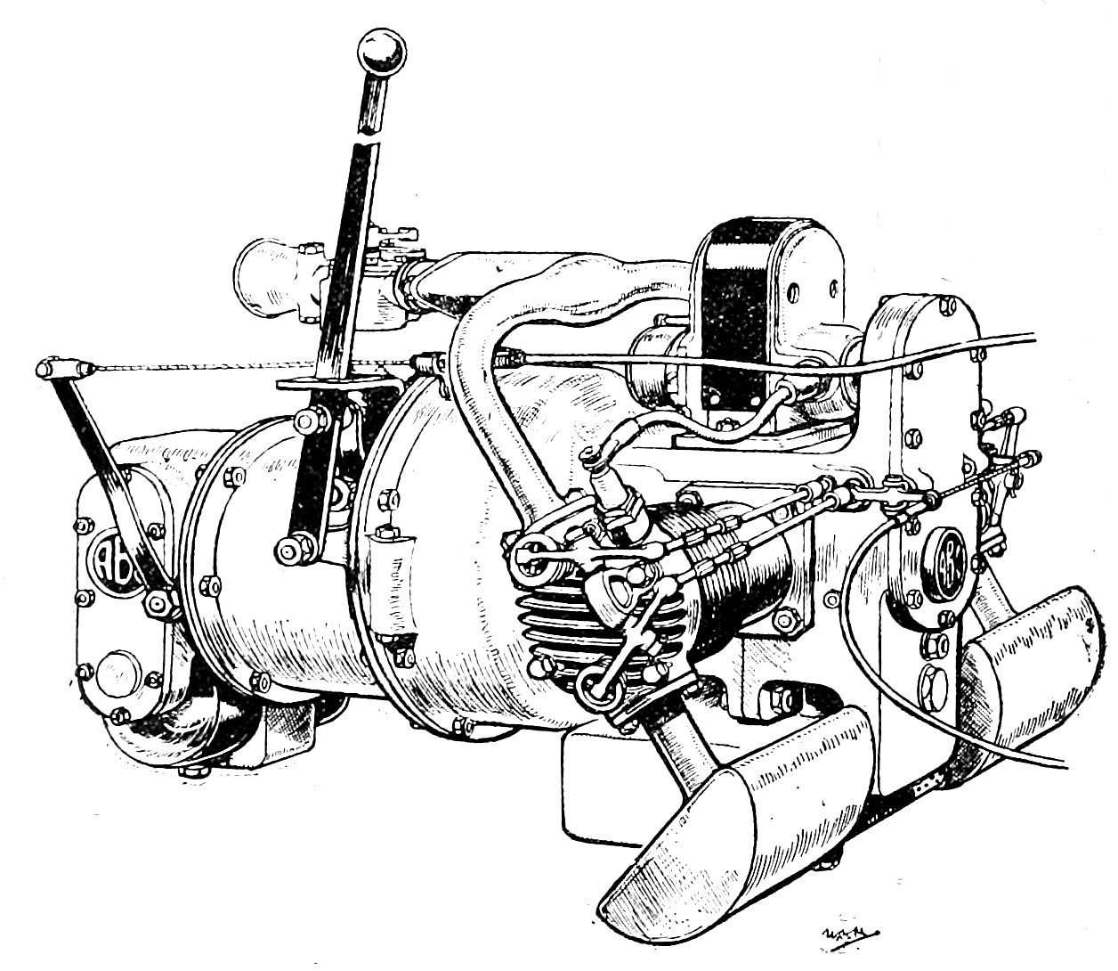
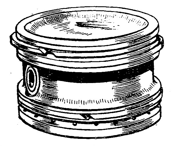
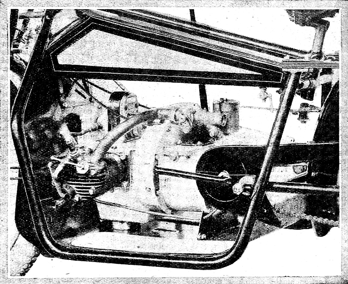
The power unit, showing position of the dynamo under the crown wheel casing.
When the early successful A.B.C. motor bicycles are recalled, and the immense experience in the construction of aero engines that the firm has had during the past four and a half years is taken into consideration, it is not surprising that the new A.B.C. clearly shows how much the firm and its designer, Mr. Granville Bradshaw, have learnt during this period.
Mechanically-minded readers naturally turn first of all to the engine, or, rather, the power unit, for in the new A.B.C. the engine and gear box are in one. As previously announced, the cylinders are placed athwart the frame, but this does not render the machine unreasonably wide.
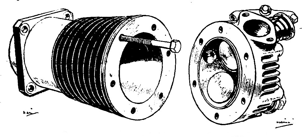
The former successful A.B.C. practice of using steel cylinders with cast iron heads has been retained. As the cylinder if is of absolutely uniform design, there are no unnecessary pieces of metal to cause hot spots and distortion.
The hemispherical cylinder heads are held on to the steel cylinders by six bolts. The valves are of the overhead type, made of unbreakable steel, with volute springs in place of the more usual helical type.
At first sight, there is a tendency to regard such items as tappet rods and rockers as being of exceedingly light construction and possessing very small wearing parts, but it must be borne in mind that in the design of the new A.B.C. lightness, as much as power, has been taken into consideration, and efficiency has been the watchword of the firm. All moving parts, such as tappets, bearings, and rocker bearings, are bushed with phosphor bronze, and the rockers themselves work on a broad arrow-shaped bracket screwed on to the cylinder head. Needless to say, the tappet rods are adjustable.
The A.B.C. cylinder and detachable head. One long holding down bolt is shown.
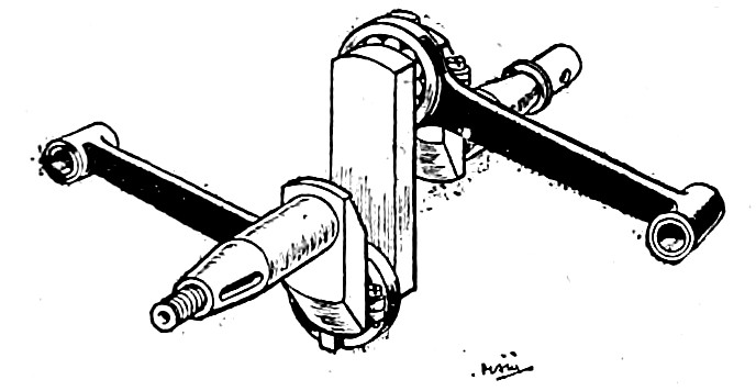
The crankshaft and connecting rods.
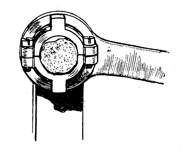
The small ends of the connecting rods are bushed to take the gudgeon pin, which also floats in the piston, and the big ends are provided with roller bearings kept in position by a split collar which is recessed to engage with the crank cheek, which prevents it from rotating on the crank pin. While these split collars are not a new feature in A.B.C. design, the method of holding them in position is quite novel. Ball-bearings are employed for the two-throw crankshaft. Die-cast aluminium pistons are adopted, having two rings at the top and a scraper ring, while the base of the piston is of slightly smaller diameter than the remainder, and is drilled with a series of holes, which relieves all oil pressure and prevents oil from being forced into the combustion heads.
At the bottom of the vertically divided crank case is a pressed steel oil sump, holding sufficient lubricant for 1,500 miles. Below this sump is situated a gear-type oil pump which is always immersed in oil. This pump forces lubricant through an oil-way in the crank case directly on to the connecting rod 'big ends, and the other working parts are lubricated by oil-mist. In the oil feed system, on the right-hand side of the crank case, there is a Rotherham oil indicator, by means of which the rider can ascertain that the oil is circulating properly.
The timing wheels are five in number, the topmost driving the magneto; next comes the driving pinion; then the camshaft pinion, which runs on ball bearings; nest an intermediate wheel for reducing the speed of the oil pump, which revolves at one-sixth of engine speed; and, finally, the oil pump wheel itself. The arrangement of the timing gear is an exceptionally pretty piece of design, and the neat little camshaft is a perfect car job in miniature.
The magneto is a special type C.A.V., and is situated on the top of the crank chamber in a most accessible position. Its position, and the design of the engine, permit of extremely short high-tension wires being used; in fact, Mr. Bradshaw told us that he had considered the advisability of doing away with the insulated high-tension wire altogether, and having a single copper wire leading from the high-tension terminals to the plugs.
Aluminium piston with concave head.
Split collar on crank pin.
Clutch and Gear Box.
Forming part of the crank case casting is the flywheel housing, the flywheel embodying the clutch. This is of the self-contained inverted cone type and Ferodo lined. The clutch spring is of ample strength, so that no adjustment should be necessary, while sufficient leverage is provided on the control to render the clutch withdrawal an extremely easy matter. This is effected by means of a twist grip on the handle-bar. The clutch is operated by a long rod passing right through the hollow five-splined mainshaft of the gear box, and actuated at the rear end by a lever on the clutch control shaft. When the clutch member is out it is entirely free, and runs on the gearshaft only. The splined shaft runs on roller bearings at its forward end, while the secondary-shaft is internally splined and also runs on roller bearings, and carries the clutch.
Change-speed gate on the side of the gear box.
The gear box provides four speeds, and the gear wheels, it may be mentioned, are ten pitch, and are the same size as those employed on light cars. It is also interesting to note that the layshaft runs on ball bearings, while the final drive to the rear is by bevel, the bevel being in.one piece with the splined shaft, and engaging with a substantial crown wheel running on two ball bearings in a casing behind the gear box. One end of this shaft carries the chain sprocket, while on the other end is a gear wheel running in oil, intended to drive the dynamo. The final drive from the sprocket to the rear wheel is by chain, the well-known A.B.C. "cush" drive being incorporated in the rear wheel sprocket. This is a system, it may be remembered, consisting of insulating the gear wheel from the shell attached to the hub by means of a series of large rubber buffers, which effectually take up the initial shocks of the engine, rendering the drive extremely smooth. The change-speed lever works in a gate on the gear box and is of the rocking pattern, and similar to that found on Rolls-Royce and other first-class makes of cars. It enables the change-speed lever to be moved from side to side without the slightest effort, so that there is no danger of upsetting the rider's balance.
The carburetter is the standard A.B.C pattern, and is warmed by means of a special jacket surrounding the branch from the main inlet pipe to the carburetter, which is connected by a small pipe to one of the exhaust ports. The position of this chamber is important, as it heats the mixture equally for each cylinder.
Since the oil supply is carried in the sump, the whole of the tank is available for petrol, so that the full capacity of well over two gallons can be devoted to the fuel. The mounting of the tank is ingenious. It is anchored rigidly at the rear while at the front it is carried on a light steel bracket cross-braced diagonally. This method of mounting, while ensuring a practically solid fixing, entirely relieves the tank of all frame stresses.
Frame Details.
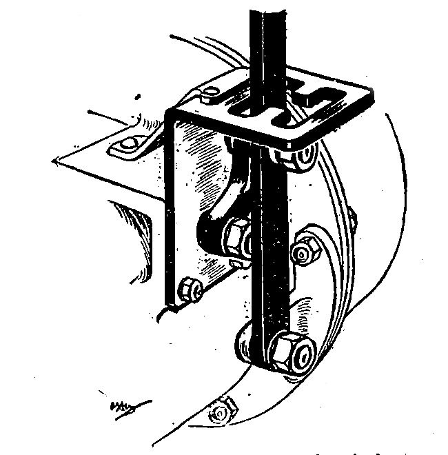
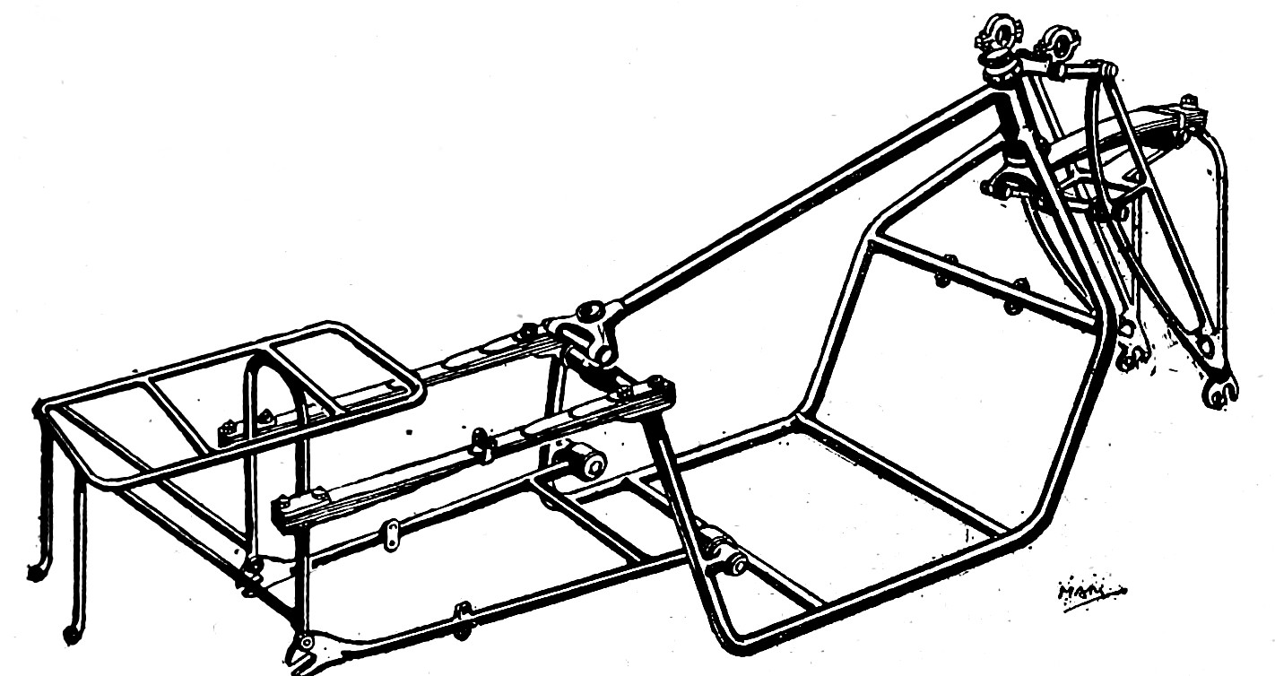
The frame is a notable departure from standard practice. There is a single top tube, while the remaining members are duplicated, forming what may be termed "a double rectangular loop." The two main members are of sufficient width to accommodate the engine, and are so designed that in the case of a fall the engine is quite safe from damage. The forward and lower portions of the frame are filled in with sheet metal, so that the under portion of the engine is protected from mud - a most important matter - while the front extension protects the working parts of the engine and the rider. Air-ways are cut in suitable positions in the tray, and are fitted with adjustable louvres, so that in the event of very bad weather being encountered, or necessity being found to pass a water splash, the draught may be cut off altogether, and the engine is' then entirely protected. Even when these doors are closed, we are given to understand, unless the engine is driven to its fullest capacity, no overheating will ensue.
Underneath the bottom shield are two cross members, not shown in the illustrations, which serve to carry the power unit, and this can be removed by undoing four bolts. The rear portion of the frame naturally is sprung, and bears upon two roller bearings situated ten inches apart on the rear members of the frame. This arrangement gives great rigidity and lateral stability, while the roller bearings prevent wear at this point.
Springing System Minus Shackles.
Showing the frame design and the front and rear springing system.
Owing to the ingenious form of springing employed, no shackles are used. The springs are practically two quarter elliptical springs joined together at the thin end by the main leaf being common to both and forming the top of one set of spring leaves and the bottom of the other. At first sight, it would seem that the midway point must be weak, but since this is the point of flexure and there is no other stress at this point, such is not the case. There is no doubt that extreme flexibility is obtained, and the riding of the machine should be most comfortable.
Since the preliminary design of the 1919 A.B.C. was reproduced in The Motor Cycle of December 12th, 1918, some modifications have been made with regard to the spring fork. The spring is of the quarter elliptic type, and the thicker end is anchored to a special stay on the front axle, so as to do away with bending stresses on the head itself. All links and pins in the front fork work in bronze bushes. Adequate means is provided for lubrication, but in case of wear these parts can be replaced.
Instead of mounting the handle-bars in the usual manner, the A.B.C. handle-bar is carried in a special bracket forming part of the forks. This bracket allows of considerable adjustment, but does not allow the handle-bars to be twisted; consequently it is impossible for any accident to occur through slipping at this point.
All wires pass through the handle-bar, and the control is simple. For instance, as mentioned before, the left-hand grip works the clutch, beneath it is the exhaust lifter, while on the right bar is situated the front brake lever. The two other levers work the spark and throttle.
Internal expanding brakes are fitted to both wheels. Mention was made in previous articles of cone brakes, but it has been found that the internal expanding type is the most satisfactory from the constructor's point of view.
The Hubs and Brakes.
Even the hubs are designed by Mr. Bradshaw, and these are provided with a larger flange on one side than on the other, the larger flange being for the attachment of the brake drums, the bolts holding the drum on to the wheel being below the points of attachment of the spokes. The spindles in both wheels are withdrawable, so that if a tyre repair should be necessary either wheel can be easily removed.
Mention has previously been made of dynamo lighting. In this case, the dynamo will be carried below the crown wheel casing, and behind it there is just room for the battery.
A kick-starter will be provided for all models. On the undershield are mounted two aluminium plates upon which the driver's feet rest. Throughout the design points of convenience have been well studied, and every care has been exercised by the manufacturers to leave nothing undone for the rider's comfort.
Method of housing the power units. The ample front and under-shied is a commendable feature.
An idea suggested to us by Mr. Bradshaw, which he may carry out, was the fitting of a toolbox underneath the crank case containing two drawers in which the tools are let into the solid wood, so that it is impossible for them to be damaged by rattling one against another.
The weight of the machine without fuel is 175 lb., and overseas purchasers will be interested to hear that the ground clearance is 6½in.
The 1919 A.B.C. has now reached its final stage, and is ready to be. Handed over to the manufacturers to produce in quantities.
We cannot refrain from congratulating Mr. Bradshaw on the excellent design of the engine, and, indeed, of the whole machine, and wishing the Sopwith company success in its enterprise.
From "The MotorCycle" - March 13th, 1919